Understanding FSW
FSW NOW WITHIN REACH
An advanced solid-state process that delivers high-strength, defect-free joints while eliminating traditional welding challenges.
FSW PROCESS
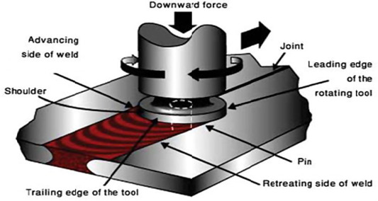
Friction Stir Welding is a solid-state joining processthat enables high-integrity bonds without reaching the melting point of the material.
The process begins with a pin type shoulder head rotating tool being plunged into the joint line. As the tool traverses the seam, the mechanical friction between the tool shoulder and the workpiece generateslocalized thermal energy, which plasticizes the metal. This softened material is then mechanically stirred and forged in the wake of the tool, resulting in a refined grain structure and a weld that is virtually free of common defects like porosity or solidification cracking. Because it remains in a solid state
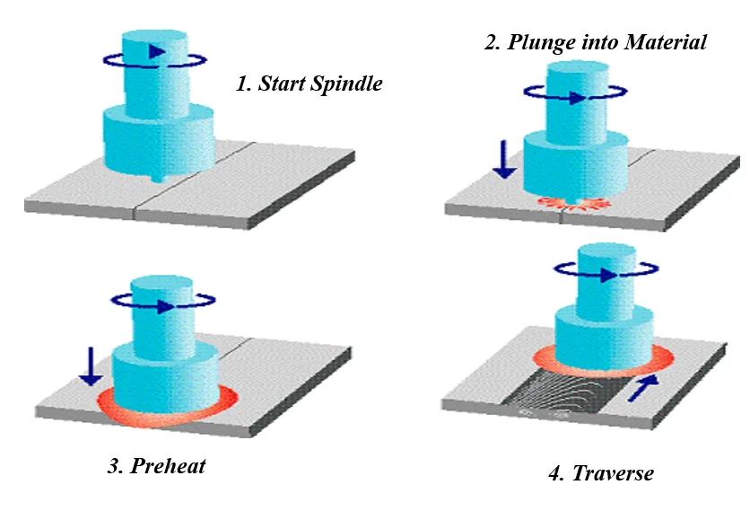
Friction Stir Welding process consists of four main stages
- Tool Rotation
- Tool Plunging
- Welding (Traversing) Process
- Tool Retraction
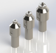
During the process, the rotating tool pin is plunged into the joint line of the materials to be welded, while thetool shoulder remains in contact with the top surface of the workpiece.
The tool shoulder plays a major role in heat generation, producing most of the frictional heat required for the welding process. This heat softens the material without melting it.
Since FSW is a solid-state welding process, the material does not reach its melting temperature. Instead, the material becomes plasticized and is stirred together by the rotating tool, forming a high-strength joint.
Typically, the process requires approximately 85–95% of the heat needed to reach the melting temperature of the material to achieve a high-quality weld.
Heat Generation
Heat Generation during FSW:
q = (2π / 3S) x µ x P x ω x Rs x η
- S - welding speed in mm / min
- µ- co-efficient of friction
- P - Normal force in ‘kN’
- ω - Rotational speed in rev/min
- Rs -Shoulder dia in ‘mm’
The heat generation q calculated from the above equation represents the required thermal energy during the welding process
The heat required for the Friction Stir Welding (FSW) process is mainly generated by the friction between the rotating tool shoulder and the workpiece surface, along with plastic deformation of the material.
Temperature Requirement
In Friction Stir Welding, the material does not reach the melting point because it is a solid-state joining process.
For producing a stable and high-quality weld, the process temperature typically reaches:
≈ 85% – 95% of the melting temperature of the weld material
At this temperature range:
- The material becomes plasticized (softened)
- The rotating tool stirs and mixes the material along the joint line
- The softened material is forged together to form a strong metallurgical bond
Maintaining this controlled heat input ensures:
- Proper material flow
- Defect-free weld structure
- High joint strength and reliability
Weld Configurations
Friction Stir Welding supports two primary weld configurations:
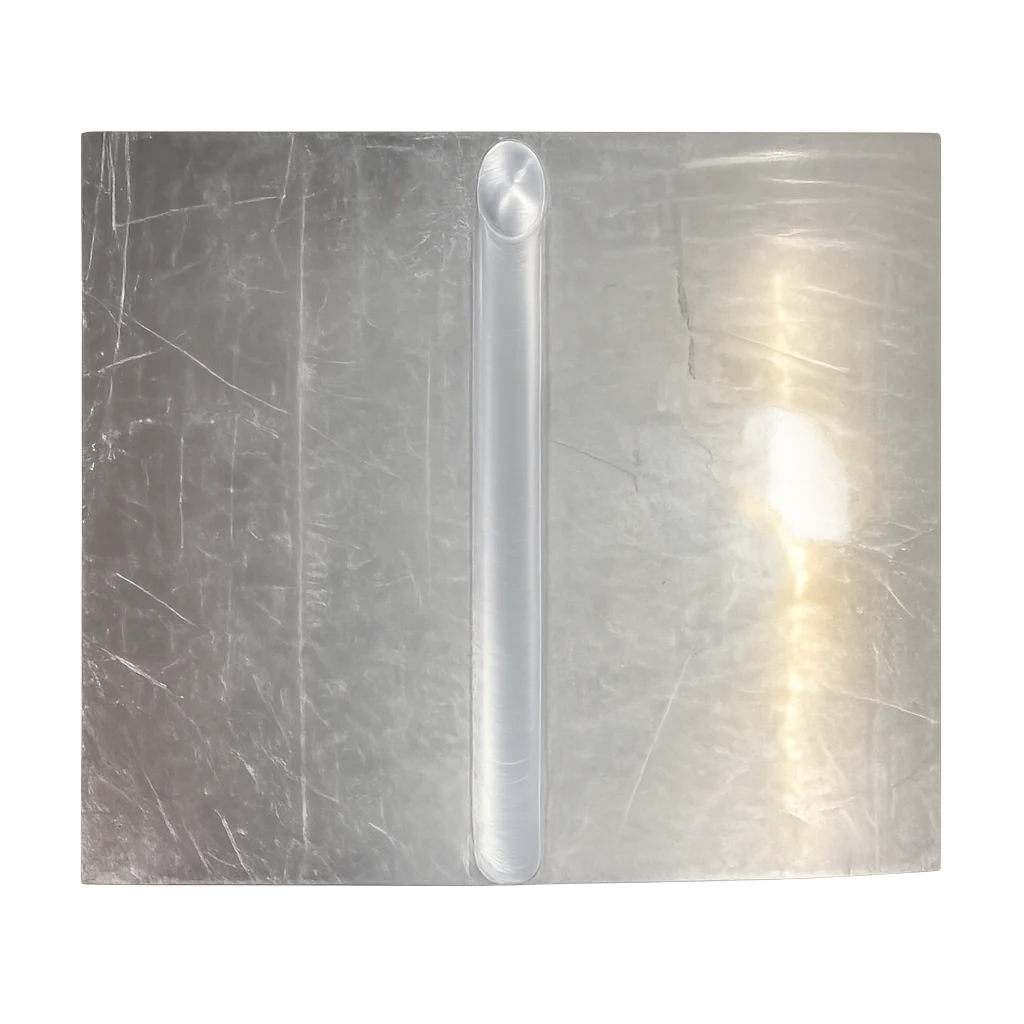
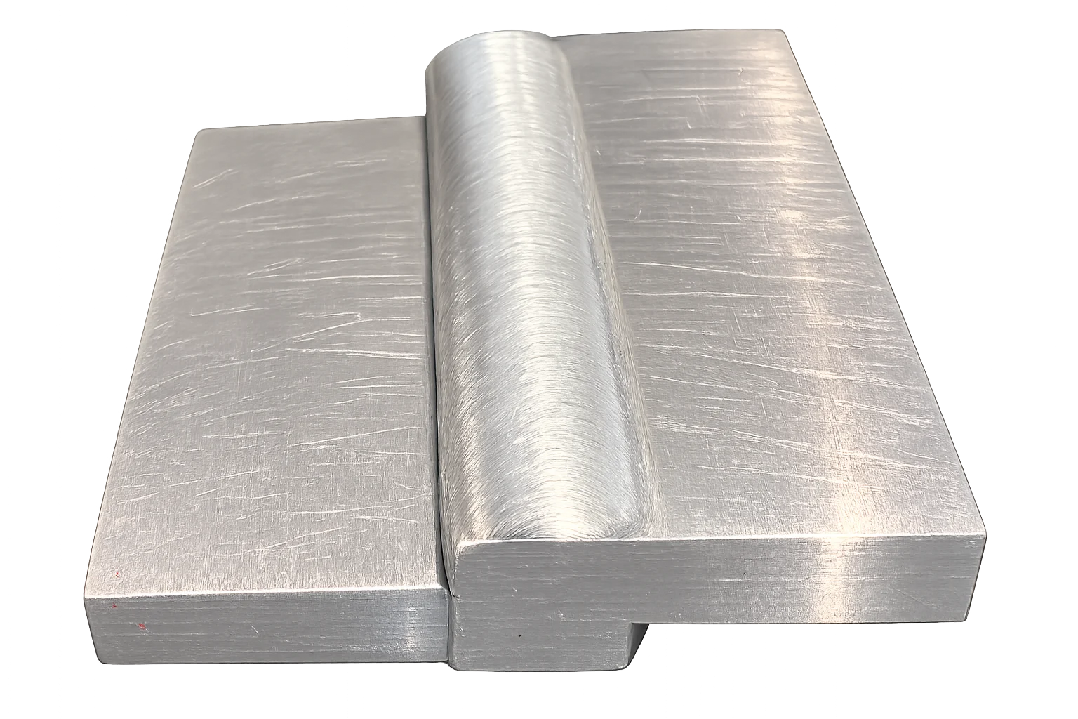
1. Butt Weld
In a butt weld configuration, two components are placed side by side in the same plane. Since FSW is a solid-state welding process, there is no melting of material, and the joint must be closely fitted.
- The parts should have no gap between them.
- Themaximum allowable gap between the two parts is typically up to 10% of the material thickness being welded.
This configuration is commonly used for joining plates or panels of the same thickness.
2. Lap Weld
In a lap weld configuration, one component is placed over another and the FSW tool welds along the overlapping region.
- Suitable for joining sheets or plates in an overlapping arrangement.
- Multiple layers of material can also be welded depending on machine capability and process parameters.
Workpiece Clamping
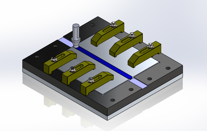
Proper workpiece clamping are critical in the Friction Stir Welding process to ensure weld quality
The workpiece must be supported by a rigid backing plate to withstand the high axial and lateral forces generated during welding. In addition:
- The parts should be secured with rigid stoppers on all four sides to prevent any horizontal movement
- Top clamping must be applied to hold the workpieces firmly against the backing plate
- This rigid fixturing arrangement eliminates part movement during tool plunging and welding traverse.
This rigid fixturing arrangement is essential to eliminate part movement during tool plunging and throughout the welding traverse
| High Heat Generation | High Rotational Speed; Low Welding Speed; High Axial Force; High Shoulder Radius; High μ | Turbulent Material Flow, Grain Coarsening; Excess Flash Formation; Formation of Defects such as Piping Defect, Tunnel Defect |
| Low Heat Generation | Low Rotational Speed; High Welding Speed; Low Axial Force; Low Shoulder Radius; Low μ | No vertical flow of material; Poor weld metal consolidation; Formation of Defects such as Pin Holes, Kissing Bond, Lazy S, Cracks. |
| Optimum Heat Generation | Optimise above parameters | Proper Material Flow, Good consolidation of weld metal; Defect Free Welds. |