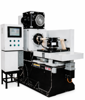
FRICTION WELDING – SERVO
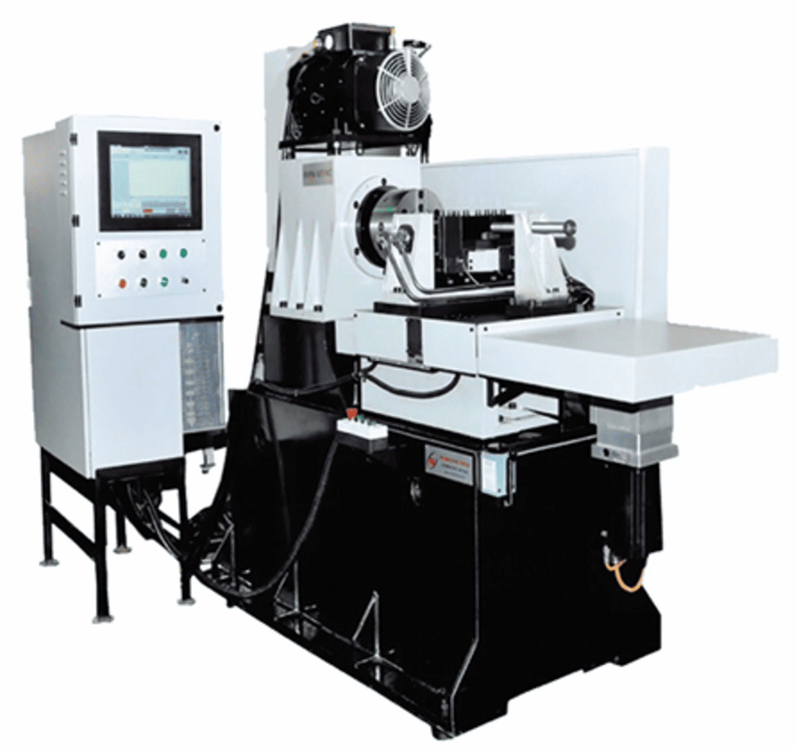
Friction Welding Process
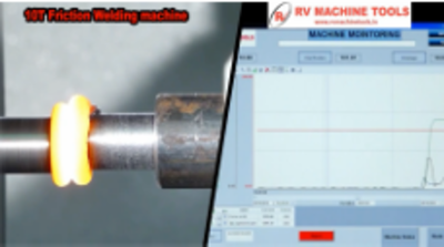
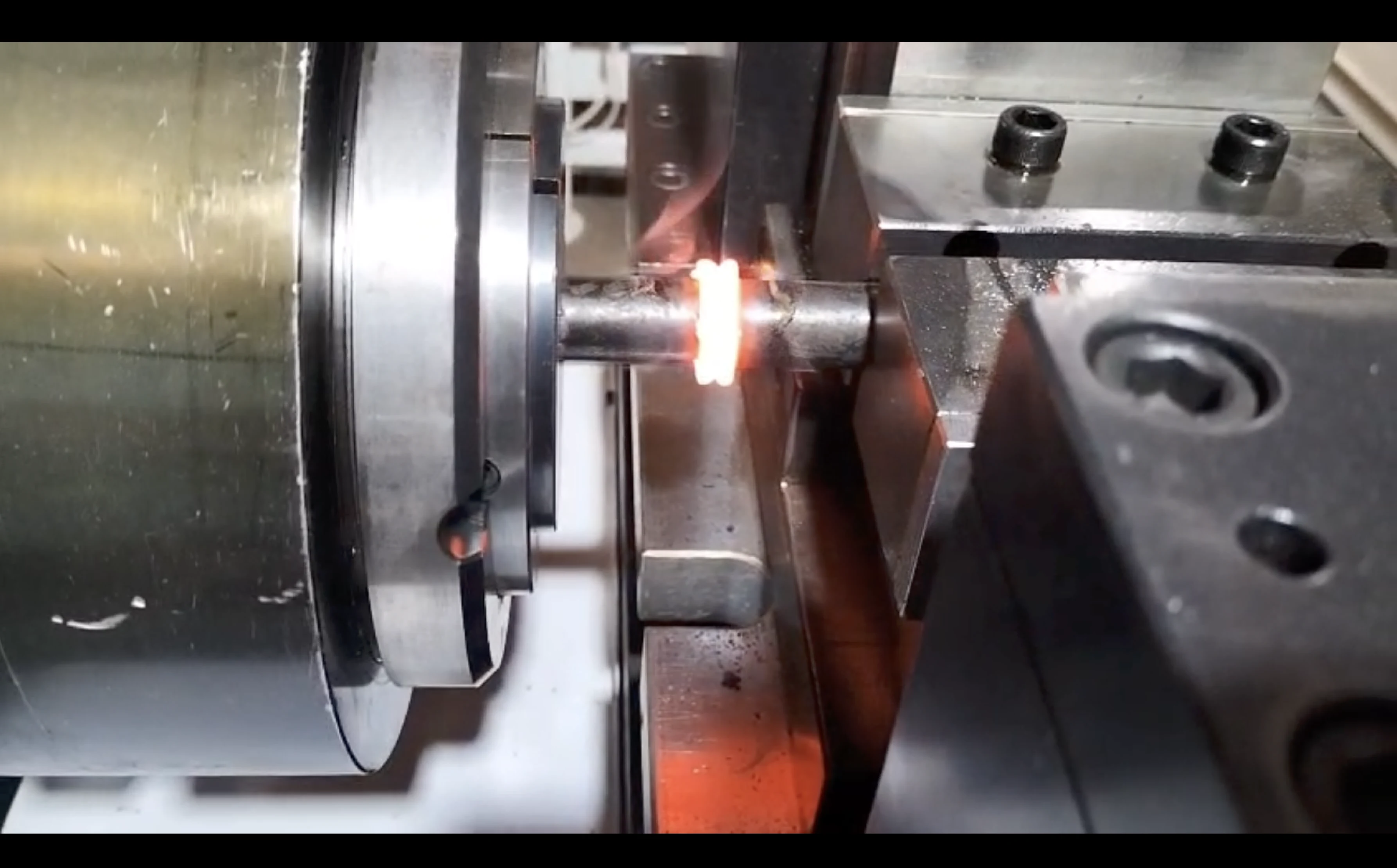
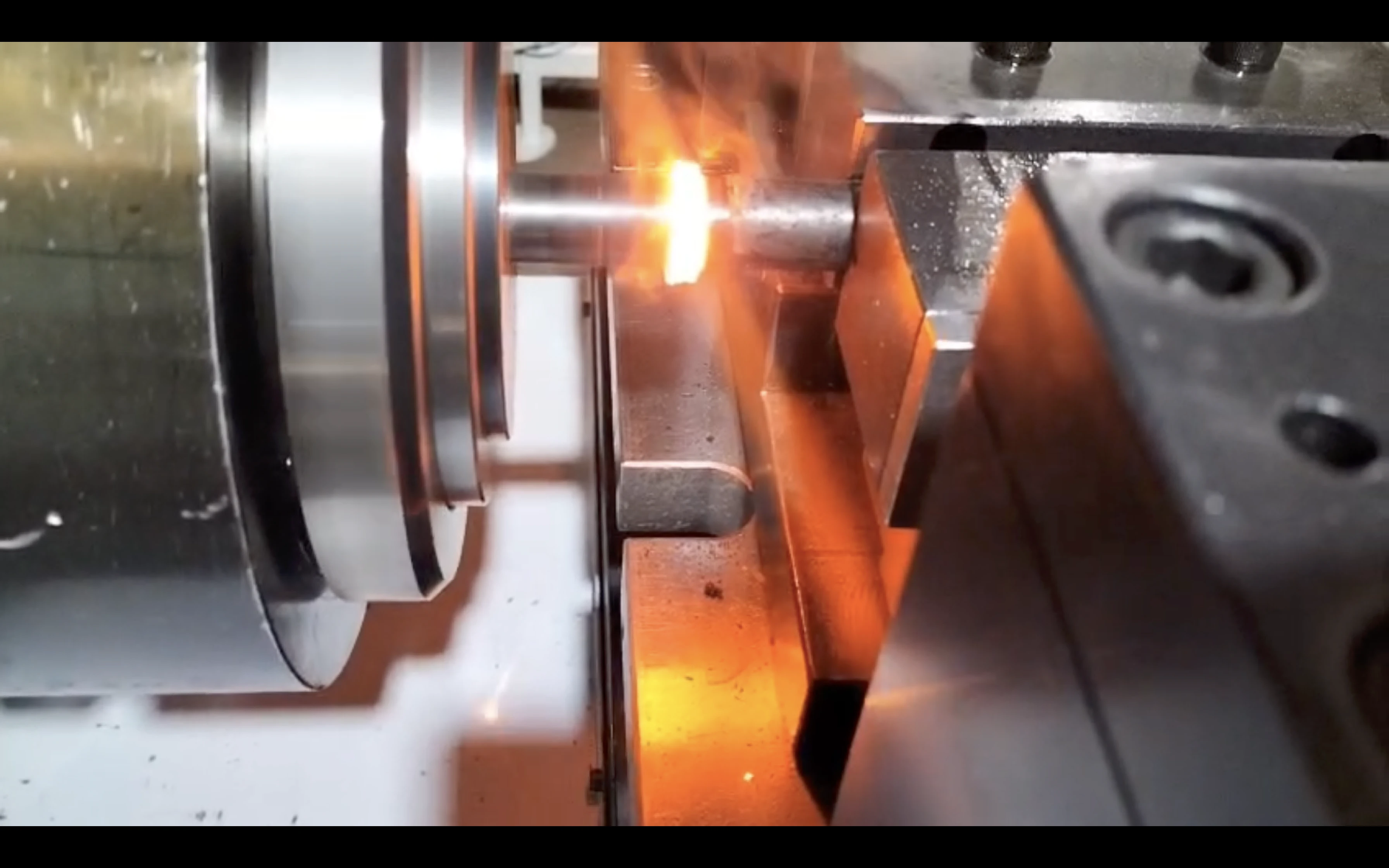
Friction welding is a solid phase welding of two similar or dissimilar materials. Using the heat generated by rubbing of two materials and when the impurities at the interfaces are removed as flash , stopping the relative motion of the components and applying a forge welding force to form a strong metallic bond.
Servo Friction Welding Technical Specification
| Models | FW6i | FW10i | FW15i |
|---|---|---|---|
| Machine Capacity | |||
| Max Forge Force | 6 Ton | 10 Ton | 15 Ton |
| Weld Dia | 8 to 19 mm | 10 to 25 mm | 15 to 35 mm |
| Weld Area Max | 284 mm2 | 490 mm2 | 950 mm2 |
| Rotating side max Dia and length | 25*200 m | 30* 250 mm | 40*250 mm |
| Non rotating side max dia and length | 30*350 mm | 50*400 mm | 50*500 mm |
| Spindle | |||
| Spindle speed max | 2500 rpm | 2500 rpm | 2000 rpm |
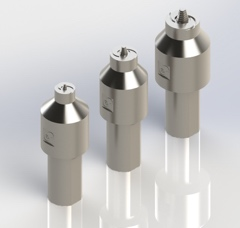
| Chuck clamping system | T980 Multi bore collet/ 3 Jaw Chuck | T 980 Multi Bore Collet / 3 Jaw Chuck | T980 Multi bore collet/ 3 Jaw Chuck |
| Self Centering Vice | |||
| Clamp Force | 10 Ton | 10 Ton | 20 Ton |
| Clamping cap (min /max) | 10 mm -30mm | 10 mm -30mm | 15 mm -50mm |
| Clamping cylinder stroke | 40 mm | 40 mm | 40 mm |
| Main Spindle | |||
| Stroke | 200 mm | 200 mm | 300 mm |
| Axis Drive | Servo Motor | Servo Motor | Servo Motor |
| Axis slide | LM Roller guide ways | LM Roller guide ways | LM Roller guide ways |
| Power Pack | |||
| Hydraulic Power | 3.7 kw/440v | 5.5 kw/440v | 7.5 kw/440v |
| Coolant Power | 1.5 kW | 1.5 kW | 2 kW |
| Controller | |||
| Control | PLC ,PC Based | PLC ,PC Based | PLC ,PC Based |
| Machine Power | 30kva /440v +- 5v | 40KVA /440v +- 5v | 40KVA /440v +- 5v |
| Machine dim (L x B x H ) | 3000 x3000 x 2200 mm | 3500 x3300 x 2200 mm | 3500 x3300 x 2200 mm |

Optional Accessories
Servo Flash Removing Slide
Increased Bar Length Stopper
Bar Feeder
Full Enclose
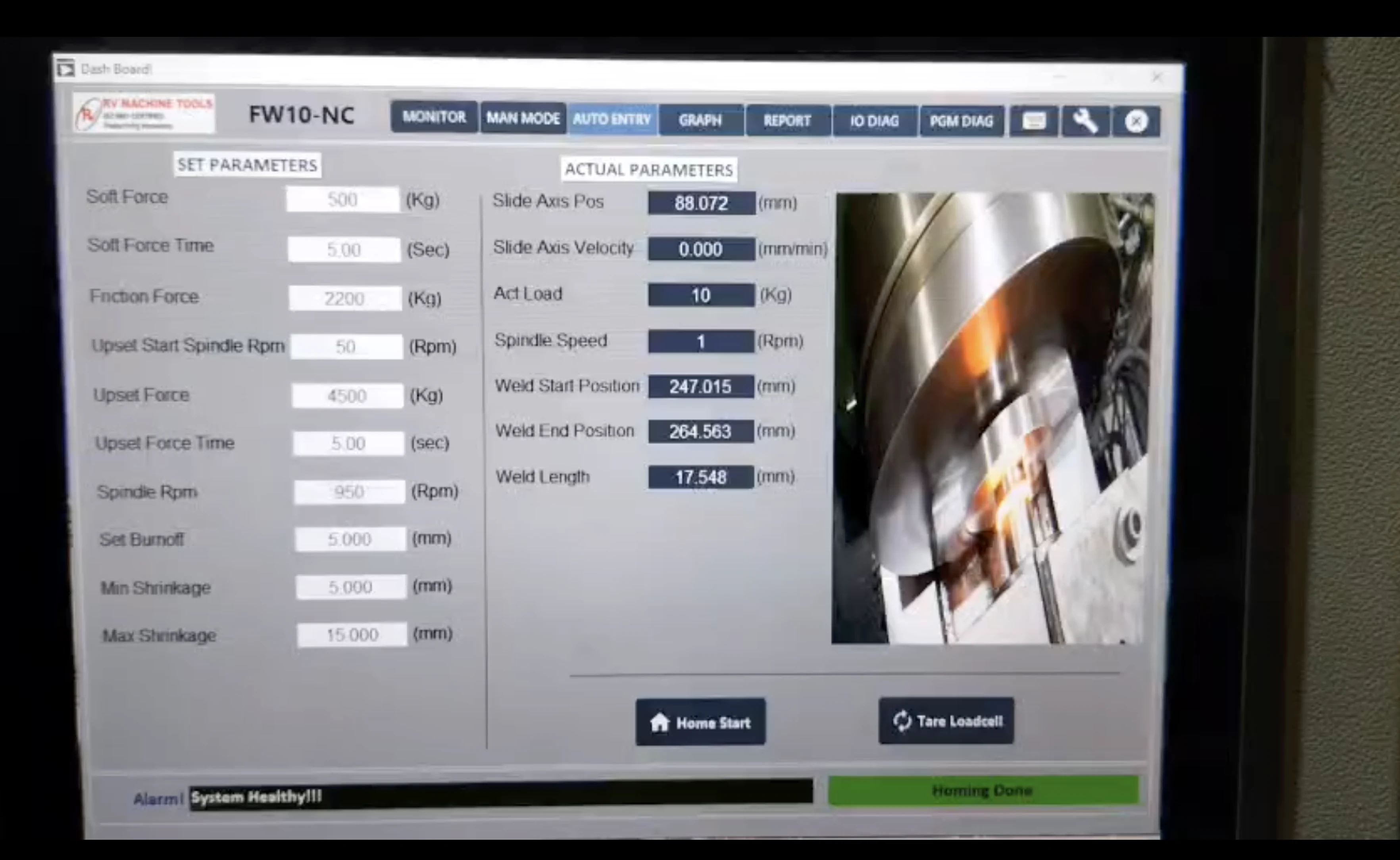
Program Screen
The friction welding program screen allows the operator to set key input parameters such as spindle RPM, Friction/forge load (force), and friction/forge time in seconds.
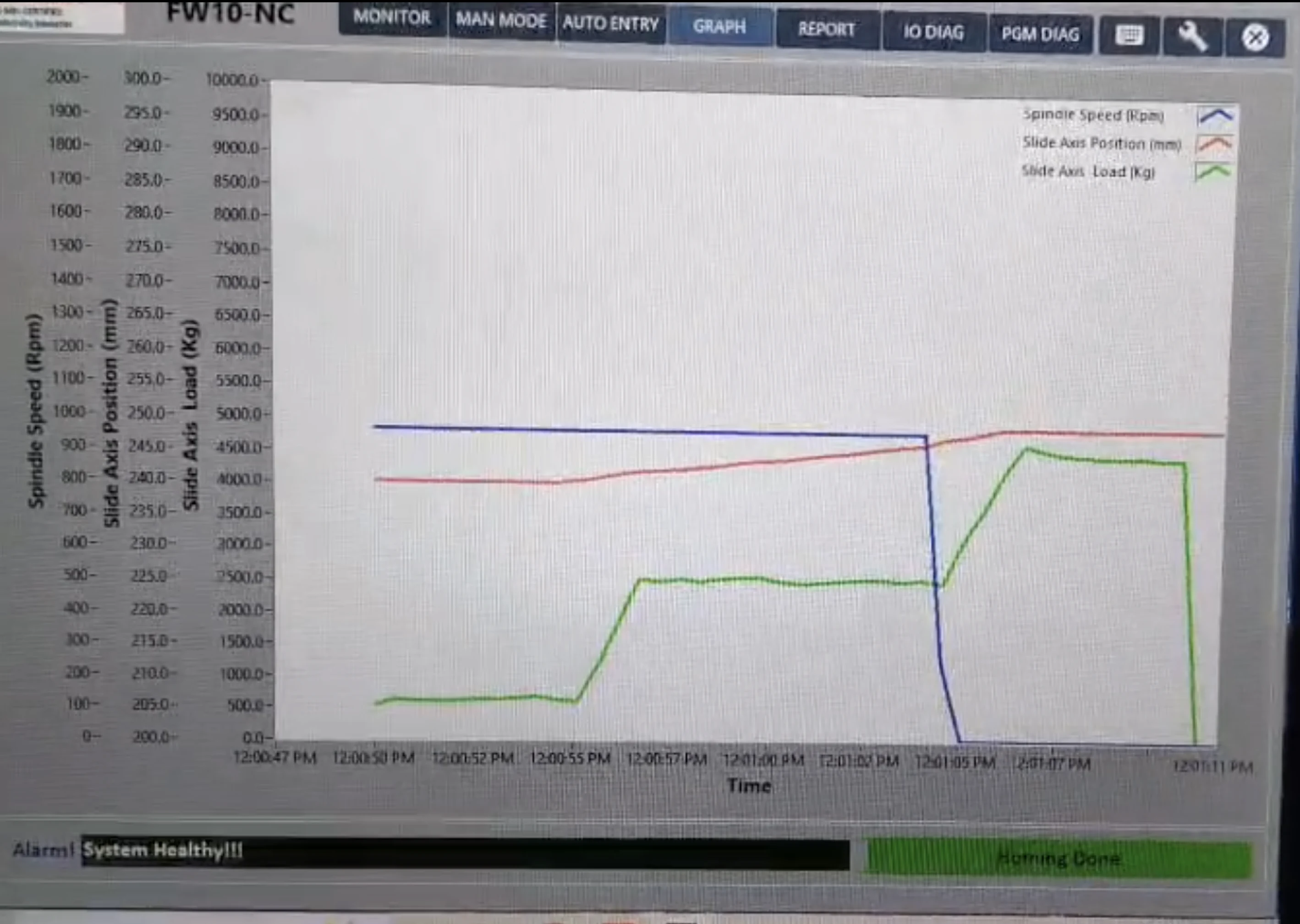
During the welding cycle, the machine continuously monitors these parameters in real time to ensure they follow the programmed values based on the selected process sequence.
The system records the actual process data, enabling the operator or customer to review, validate, and fine-tune the parameters for optimal weld quality and repeatability.
Interlocks
An emergency stop switch is provided for all control circuits. Activation of the emergency switch immediately disables all machine operations. Machine commands will not be accepted unless the hydraulic system is activated and pressure is within the operating range.
The spindle cannot be started unless the chucking system is properly engaged and clamped. The automatic cycle will function only when both chuck and clamp are in the ON (clamped) position.
If the lubrication or hydraulic oil level drops below the minimum limit, the machine will stop automatically, and an error message will be displayed on the operator panel. A reset switch is provided to clear faults and re-enable machine operation after the alarm condition is rectified.